> For the complete documentation index, see [llms.txt](https://docs.enlyze.com/llms.txt). Markdown versions of documentation pages are available by appending `.md` to page URLs; this page is available as [Markdown](https://docs.enlyze.com/en/connect/ot-connectivity/supported-industrial-protocols/fins.md).

# FINS

This guide walks you through connecting data sources that communicate via the FINS protocol. FINS (Factory Interface Network Service) is [Omron](/en/connect/ot-connectivity/supported-controller-brands/omron.md)'s proprietary protocol and is used by the classic SYSMAC families up to the modern Sysmac controllers. ENLYZE connects these controllers via FINS over Ethernet (TCP, default port `9600`).

{% hint style="warning" %}
**Prerequisite: knowledge of the memory areas**

FINS addresses data through memory areas (e.g. D, CIO, W) rather than symbolic tags. To record the right variables, we therefore need the relevant memory addresses of the controller. There are two ways to obtain them:

* The machine manufacturer or controller programmer tells us the relevant memory addresses directly.
* We receive the controller's project file (CX-Programmer `.cxp` for Classic, CS1, CJ, and CP controllers; Sysmac Studio `.smc2` for NJ and NX) and derive the memory areas from it.
  {% endhint %}

## Supported devices

FINS is supported by a wide range of Omron controllers. For a complete overview of the families and devices, along with the matching **Target PLC** setting, see the [Omron page](/en/connect/ot-connectivity/supported-controller-brands/omron.md). Any FINS-capable device with an Ethernet interface can be connected, including:

* Omron CV / CVM1 (Target PLC: *Classic*)
* Omron CS1 (CS1G, CS1H, CS1D)
* Omron CJ1 (CJ1G, CJ1H, CJ1M) and CJ2 (CJ2H, CJ2M)
* Omron CP series with Ethernet (CP1L-EL / -EM, CP2E-N, CP1H with Ethernet option)
* Omron Sysmac NJ (connected via FINS through its Ethernet port)

{% hint style="info" %}
We have successfully connected controllers via FINS up to and including the NJ series. The **NX** and **NY** families are likely connectable via FINS as well but have not yet been connected in the field. For all controllers from the CS1 (1999) onward, including NJ, NX, and NY, use the *CS1 or newer* setting.
{% endhint %}

## Required information

<table><thead><tr><th width="293.6058349609375">Information</th><th>Comment</th></tr></thead><tbody><tr><td>Name</td><td>Pick a descriptive name for your data source</td></tr><tr><td>Edge Device used for the connection</td><td>Printed on a sticker on each Edge Device. Follows the pattern <code>adjective-scientist</code></td></tr><tr><td>Machine</td><td>Each data source is assigned to exactly one machine</td></tr><tr><td>Manufacturer</td><td>Omron</td></tr><tr><td>IP address</td><td>The IPv4 address of the controller. It must be <a href="/pages/NOoLZt9S2VJxBY2IkzbA">reachable</a> from the Edge Device</td></tr><tr><td>Port</td><td>Default: <code>9600</code> (FINS over Ethernet, TCP)</td></tr><tr><td>Target PLC</td><td>Generation of the Omron controller, e.g. <em>CS1 or newer</em>.<br><a href="#target-plc">→ How to find the right target PLC type</a></td></tr><tr><td>Local address</td><td>FINS address of the Edge Device in <code>NETWORK.NODE.UNIT</code> form.<br><a href="#local-and-remote-address">→ How to determine the local address</a></td></tr><tr><td>Remote address</td><td>FINS address of the controller in <code>NETWORK.NODE.UNIT</code> form.<br><a href="#local-and-remote-address">→ How to determine the remote address</a></td></tr></tbody></table>

## Understanding the connector details

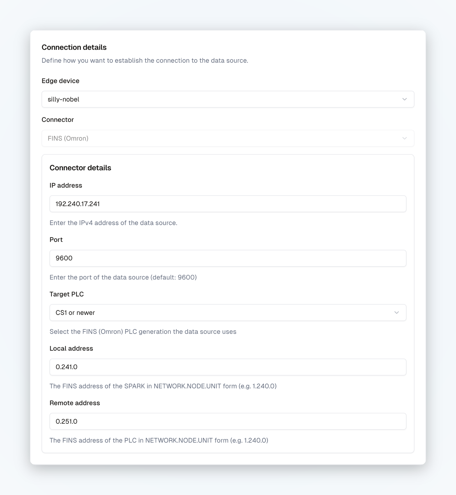
Connecting via FINS requires three FINS-specific values in addition to the IP address and port: the **Target PLC**, the **Local address**, and the **Remote address**.

<figure><img src="/files/qys0jOqDEmcudKQPLFdU" alt="Connector details for an Omron data source with IP address, port, target PLC, local address, and remote address"><figcaption><p>Connector details of an Omron data source in the ENLYZE Platform</p></figcaption></figure>

### Target PLC

**Target PLC** defines which Omron generation the data source uses. The selection determines how the connector addresses the controller's memory areas (e.g. D, CIO, W, H), since the FINS memory model differs between generations. Two options are available:

* **Classic**: Omron controllers introduced before the CS1 (1999), mainly the CV / CVM1 series.
* **CS1 or newer** (default): the CS1 and every later generation, i.e. CS1, CJ1, CJ2, the CP series, and the Sysmac families NJ, NX, and NY.

To find out which setting to choose for your device, see the [device overview on the Omron page](/en/connect/ot-connectivity/supported-controller-brands/omron.md). When in doubt: anything from the CS1 (1999) onward uses *CS1 or newer*.

### Local and remote address

FINS addresses every device through a three-part address in `NETWORK.NODE.UNIT` form (e.g. `1.240.0`). The two fields describe the two endpoints of the communication:

* **Local address**: the FINS address the **Edge Device** uses to announce itself on the FINS network. This is how the controller "sees" the Edge Device.
* **Remote address**: the FINS address of the **controller** the Edge Device should communicate with.

The three parts of the address mean:

<table><thead><tr><th width="200">Part</th><th>Meaning</th></tr></thead><tbody><tr><td><strong>NETWORK</strong></td><td>Address of the FINS network (0–127). In practice the value <code>0</code> has proven reliable and fits the vast majority of setups. In rare cases <code>1</code> is required, for example when additional modules are occupied on the rack.</td></tr><tr><td><strong>NODE</strong></td><td>Node address of the device on the network (1–254). With FINS over Ethernet, the node address often matches the last octet of the IP address (e.g. IP <code>192.168.0.220</code> → node <code>220</code>). This is not mandatory, however, and does not apply to all controllers.</td></tr><tr><td><strong>UNIT</strong></td><td>Unit address within the device. The CPU is reached via <code>0</code>. Communication modules have different unit numbers.</td></tr></tbody></table>

#### Example

Suppose the controller has the IP address `192.168.0.220`:

* **Remote address** (controller): the node address matches the last octet of the IP, i.e. `220`. With network `0` and unit `0` (CPU) this gives `0.220.0`.
* **Local address** (Edge Device): the Edge Device interface in the controller's network has, in this example, the IP address `192.168.0.250`. This yields node address `250`, and with network `0` and unit `0` the local address `0.250.0`. What matters is only that the node address is unique on the network.

{% hint style="info" %}
**Where do I find the values for the remote address?** The node and unit address of the controller are stored in the configuration of the Ethernet module or the built-in Ethernet port (e.g. in CX-Programmer or Sysmac Studio, sometimes via rotary switches on the module). The node address is often set to match the last octet of the IP address. In setups without FINS routing, the network address is usually `0`.
{% endhint %}

{% hint style="warning" %}
The **local address** of the Edge Device must be unique on the FINS network and must not collide with the node address of the controller or other devices. For controllers that use fixed IP-to-node tables, the Edge Device node must be entered there for communication to succeed.
{% endhint %}

{% stepper %}
{% step %}

#### Connect the data source to the network

If not already done, establish a network connection between the data source and the Edge Device. See [Integration scenarios](/en/connect/integration-scenarios.md) for the available options.

{% hint style="info" %}
FINS over Ethernet uses two channels: the connection is established and controlled over **TCP** on port `9600` (control channel). The controller then delivers the actual data stream over a second **UDP** port (data channel). Both channels must be reachable between the Edge Device and the controller. When configuring firewalls, make sure not only the TCP port is open.
{% endhint %}
{% endstep %}

{% step %}

#### Create the data source

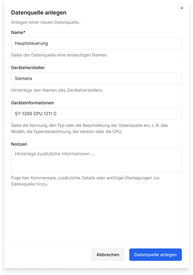
Open the [ENLYZE Manufacturing Data Platform](https://app.enlyze.com/platform), select the machine you want to add the data source to, and click *+ Data source*.

Enter the device details first.

<figure><img src="/files/69pF4p3KjwqDvCxrYaVg" alt="" width="312"><figcaption><p>Creating a data source in the ENLYZE Platform</p></figcaption></figure>
{% endstep %}

{% step %}

#### Add connection details

To establish the connection and start recording data, enter the connection details.

Click *Add connection details* and enter the IP address, port, target PLC, local address, and remote address as described above. Then *save* the values.

<figure><img src="/files/qys0jOqDEmcudKQPLFdU" alt="Connection details of an Omron data source with edge device, connector, and connector details"><figcaption><p>Connection details of an Omron data source in the ENLYZE Platform</p></figcaption></figure>
{% endstep %}

{% step %}

#### Add variables

FINS addresses data through memory areas (e.g. DM, CIO) rather than symbolic tags. Variables are therefore added manually by their FINS memory address. Have the relevant addresses from the PLC program ready.

{% hint style="warning" %}
No data is recorded until you select the [variables](/en/variable-mapping/contextualisation.md) to record. Follow our variable onboarding flow.
{% endhint %}
{% endstep %}
{% endstepper %}

## See also

* [Tips & practical notes](/en/connect/ot-connectivity/supported-industrial-protocols/fins/known-issues.md): notes on operating the FINS connector, e.g. how to find a controller with an unknown address.